
This article explores the OSI (Open Systems Interconnection) model and its relevance to network troubleshooting, particularly within the context of RouterOS. It stems from a real-world issue encountered while expanding a virtual OS system and the subsequent "blame game" that ensued.
The OSI Model: A Practical Overview
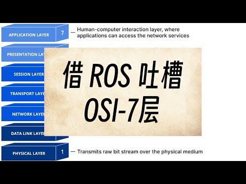
While the OSI model traditionally comprises seven layers, in practice, a simplified five-layer model is often sufficient. A common approach is to combine layers 5, 6, and 7. The OSI model provides a framework for understanding network communication, and understanding each layer helps in pinpointing network issues.
-
Layer 1: Physical Layer (e.g., optical or electrical signals).
-
Layer 2: Data Link Layer (MAC addresses, VLANs).
-
Layer 3: Network Layer (IP addresses, routing).
-
Layer 4: Transport Layer (TCP, UDP).
-
Layers 5-7: Session, Presentation, and Application Layers (often combined in modern protocols like HTTPS).
Why the OSI Model Matters
The speaker often refers to specific layers in his videos to provide context. For example, mentioning that something operates on the 2nd or 3rd layer. This detailed breakdown helps in understanding the functionality and limitations of network devices and protocols.
The Virtual Environment Expansion Issue
The speaker's company deployed a virtual OS system in their data center. When expanding from a double-node to a triple-node setup, an unexpected failure occurred.
The Blame Game Begins
The initial reaction involved pointing fingers, with the switch (a MikroTik switch) and the firewall being primary suspects. The conversation revealed a misunderstanding regarding network bridging.
The Bridge Configuration
The boss questioned the necessity of a network bridge. The speaker explained that in MikroTik, interfaces could function as either Layer 2 or Layer 3 interfaces. Placing an interface on a bridge makes it a Layer 2 interface.
Layer 2 vs. Layer 3 Interfaces
A crucial distinction is whether an interface has an IP address. If an interface has an IP address, it's a Layer 3 interface. In MikroTik, an interface within a bridge is a Layer 2 interface, even if it has an IP address, because it operates as a sub-interface of the bridge. If an interface is configured with an IP address and not attached to a bridge, it will be considered a Layer 3 interface.
Technical Support and Core Networks
During troubleshooting, the support team suggested the issue might stem from the software's core network requirements (similar to Ceph in PVE). The core network required the core networks to communicate on the second layer, but the speaker argued that such was not the case.
Network Card Suspicions
The network card on the third node became another point of suspicion. The support team suggested that the network card (a Broadcom) might be the cause, recommending Intel or Mellanox instead.
Deep Dive into Layers 1-4
The speaker then breaks down the first four layers of the OSI model.
Layer 1: Physical Layer
Deals with the physical medium (e.g., cables, wireless signals). In Winbox, this layer is visible when configuring interface speed and duplex settings.
Layer 2: Data Link Layer
Focuses on MAC addresses and local network communication. VLANs, MACsec (Layer 2 encryption), and related functions operate at this layer.
Layer 3: Network Layer
Handles IP addressing and routing. IPv4 and IPv6 are the primary protocols.
Layer 4: Transport Layer
Governs end-to-end communication using protocols like TCP and UDP. Firewalls often operate at this layer, filtering traffic based on TCP/UDP ports. Protocols like IPIP and GRE also function at this layer.
The Application Layer and Tunneling
Layers 5-7 (Session, Presentation, and Application) are often combined. Protocols like HTTPS rely on encryption (SSL/TLS) and more complex data exchange.
Tunneling vs. Agent Protocols
The speaker contrasts complete tunnel protocols (e.g., WireGuard, IPsec) with agent protocols, used for accessing resources like NAS devices remotely. Tunnel protocols transmit all the data from the lower layers, whereas agent protocols only transmit the essential data by reassembling it on the application layer, which allows for better overall efficiency.
Why Agent Protocols Can Be More Efficient
Agent protocols can be more efficient because they avoid issues like MTU (Maximum Transmission Unit) fragmentation and potential retransmission problems associated with TCP within tunnels. Complete tunnel protocols may duplicate the functionality of TCP/IP.
Conclusion: Practical Implications for RouterOS Users
The speaker concludes that understanding the first four layers of the OSI model is crucial for RouterOS users, especially concerning bridging configurations. Knowing that adding an interface to a bridge makes it a Layer 2 interface is essential for avoiding misconfigurations and troubleshooting network issues.